

| 05-14-2016, 08:35 PM | #1 |
|
First Lieutenant
 
163
Rep 387
Posts |
DIY PSU Build for Flashing
EDIT: Photo links are dead. Thanks to Pierre26, we now have a PDF backup. It is attached at the bottom of this post.
This build uses old HP server power supplies which can be obtained on ebay for dirt cheap. The PSU is called DPS600PB. 1 or 2 DPS600PB (ebay) jumper wires (commonly used with arduinos, ebay) wire cutting and soldering supplies heatshrink in various sizes automotive jumper cables 4mm bullet connectors (optional if you want your setup to be detachable, amazon) 1k ohm potentiometer (i got a 10 pack from amazon, but you can find these anywhere) multimeter Disclaimer: I take no responsibility for injury to yourself, others, your pets, your car, or anything really that result from following these instructions. It is currently unconfirmed whether or not to isolate the DC ground within these PSU when running them in parallel is the right thing to do. The instructions have been included, but may be skipped if you are confident it is not needed. Each of these PSUs has a 12v rail capable of 47A (someone on youtube tested up to 55A before it shut off). A single one of these should be enough to flash the car based on what ferrarif1 said his real PSU was reading during flashing (20+ amps). I decided to wire mine in parallel to double the total amps because these PSUs have a current sharing pin (pin 11), not to mention the PSUs came in a two pack. These PSUs are often used to charge RC lipo batteries. This page was very helpful, but I did not follow all of the instructions because I combined steps from other guides. All photos were taken from here: http://www.ultimaterc.com/forums/sho...d.php?t=174225 Remove all external screws except for the handle. 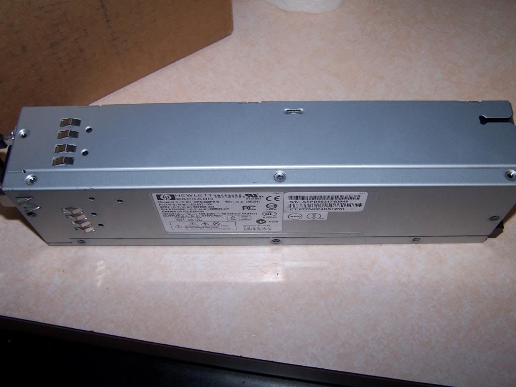 You don't have to, but i drilled off the red handle. 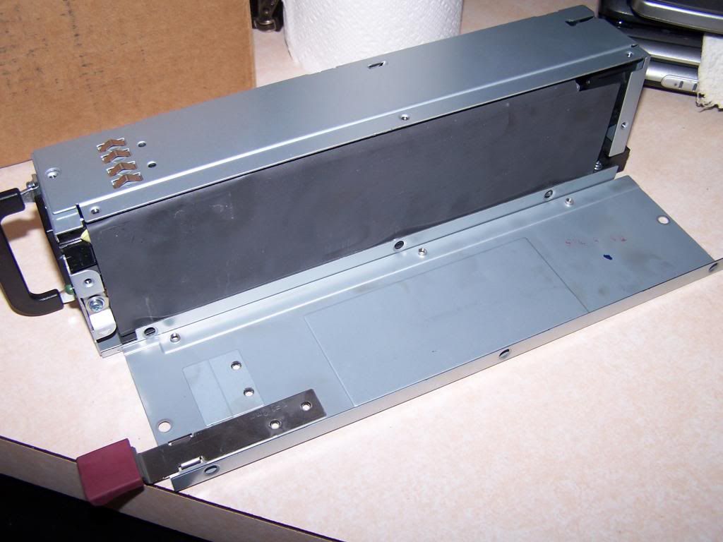 Using the top cover that you just removed as a knife, you're going to break the adhesive between the black insulation and the side panel at the top in this photo. 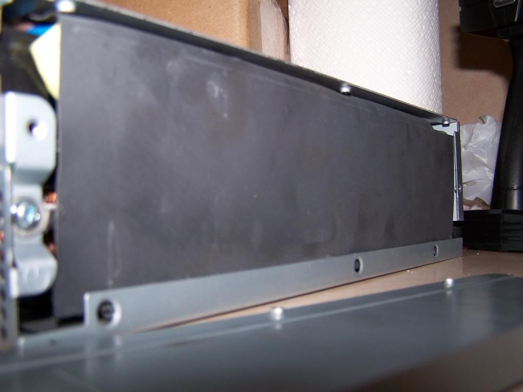 Now that the adhesive is broken, you should be able to slide the side panel apart like this. Then remove the fan screws. 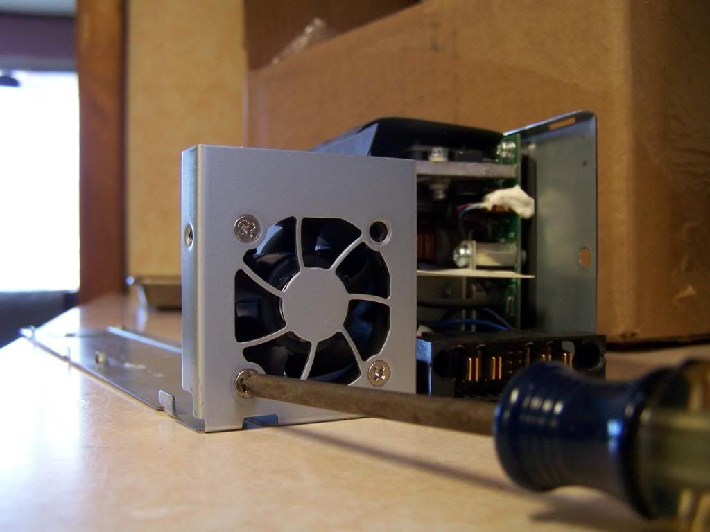 Once inside, you're going to want to isolate the DC ground in these two places. For the top arrow, I took that screw out, pried the board away from the standoff slightly, and placed 3 layers of electrical tape on the bottom side of the board. For the bottom arrow, you have to break those two connectors. It was pretty easy to do with needle nose pliers. 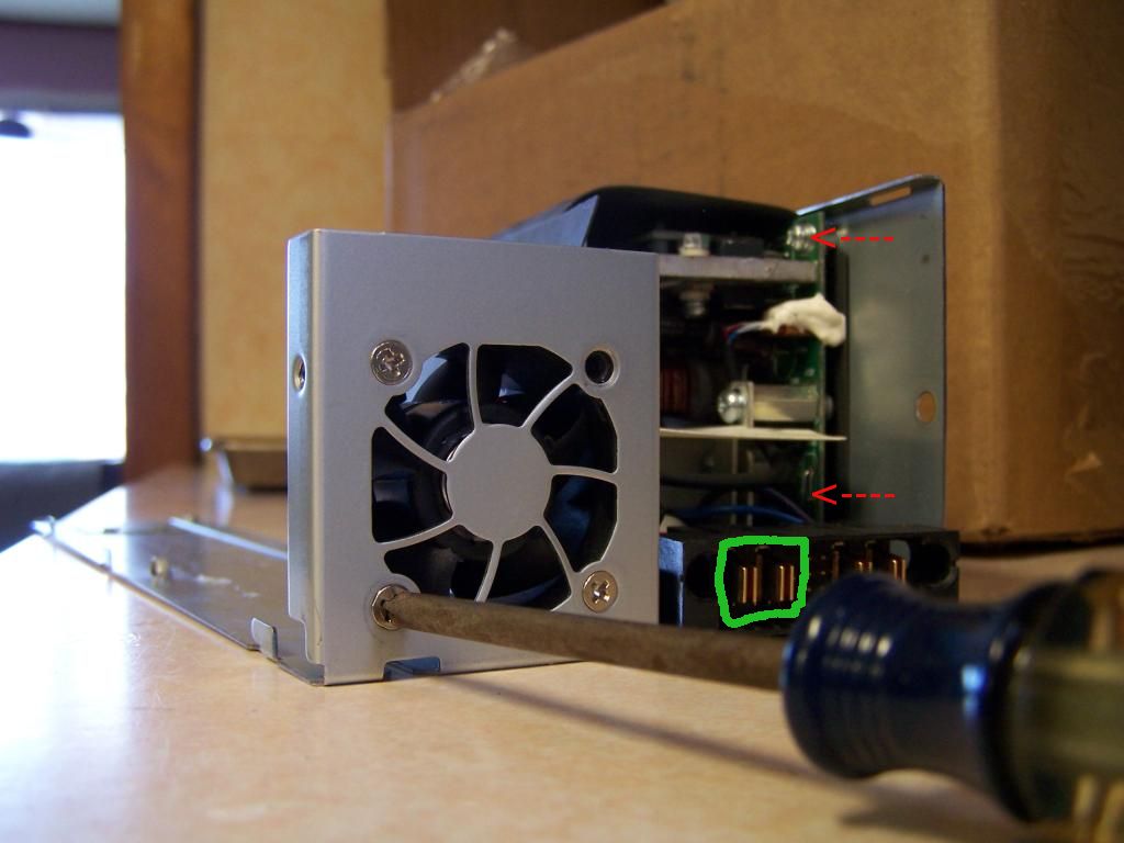 Now, reassemble the PSU. Using 4 ends of the arduino jumper wires, I connected pins 4 6 8 10 by stripping the other end, twisting them and soldering them together. This deviates from the link I posted above. They use a switch, but mine powers on when you plug it in. FAN 1 2 3 4 5 6 7 8 9 10 11 12 My potentiometer had 3 pins. I used pin 1 and 2. Take your potentiometer and test the resistance using the multimeter on those two pins. Make sure it is around 400-500 ohms. I then used jumper cables to connect those pins to pin 3 and 9 on the PSU. This will be your voltage controller.  Plug it in and attach your multimeter in DC voltage mode onto the 12v power connectors, the big slots on both side of the pins we just connected. The left side is ground and the right side is 12v. Adjust your potentiometer until the output voltage is reading 13.5-13.6v. Do not go much higher as the PSU has over voltage protection at 13.8 and will shut off. Due to some conflicting information on the internet, the over voltage protection might be triggered at 13.65v. You now have a working PSU! How you want to connect the PSU to the jumper cables is up to you. You could cut solder the jumper cables directly to the 4 terminals, or use bullet connectors to make it modular like I did. To solder onto all 4 terminals, split your stranded wire in half and tin them together. Then, I was able to force them into the connectors and then solder them to the connectors pretty easily. 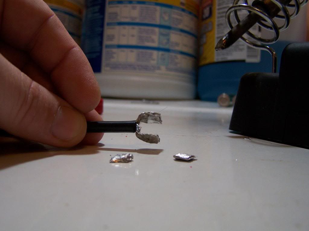 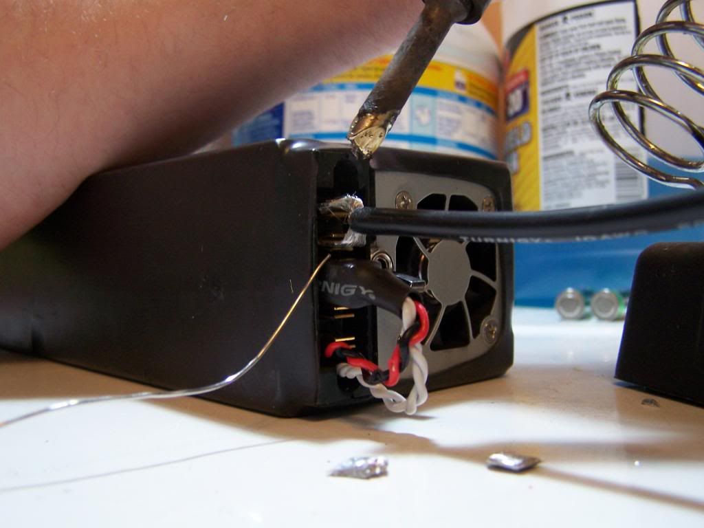 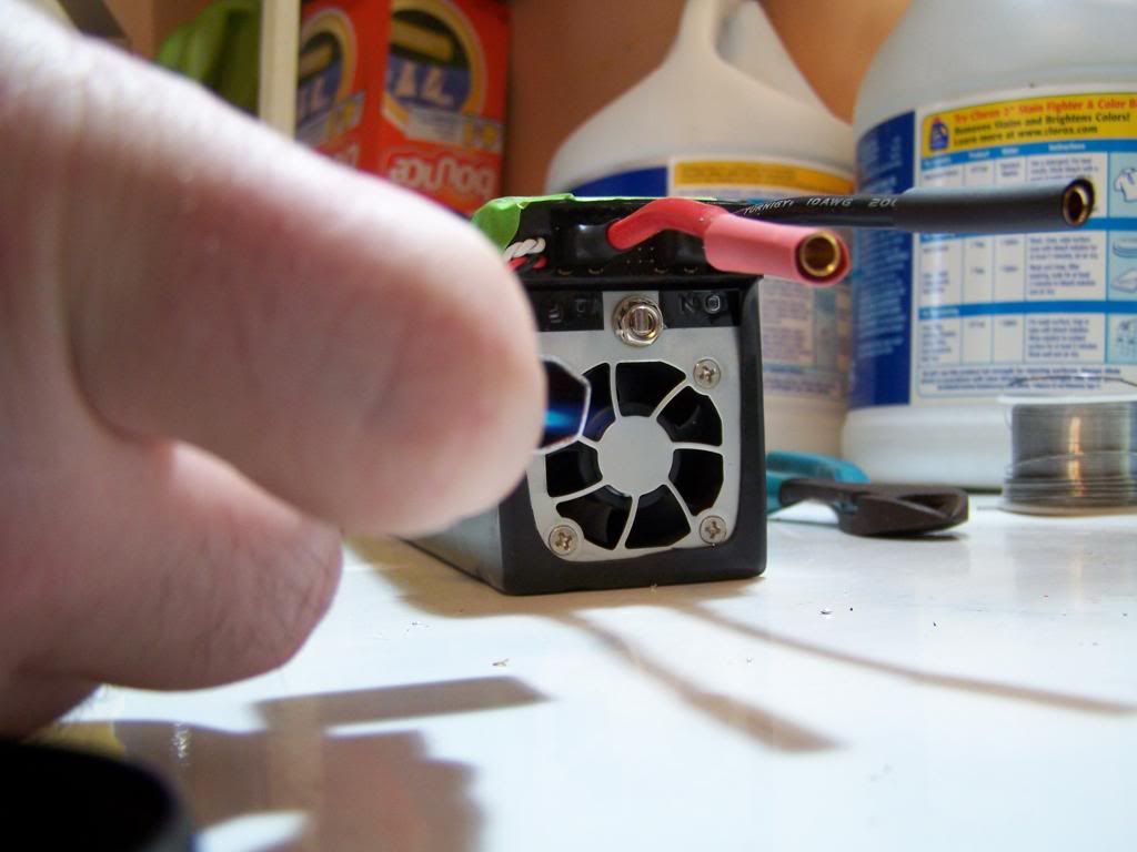 The very last step only applies if you are using two PSU in parallel like I did. You just need to take another jumper cable and connect pin 11 on both PSU together. That's it! Here's my finished setup:  My PSUs were set to 13.5v and I think I was losing voltage due to the resistance of the long jumper cables and my crappy soldering. The car's battery terminals were reading 13.30v on my multimeter during flashing and did not budge the whole time. To update my car, I used ESYS with 58.3 full data and this PDF: http://www.bimmerfest.com/forums/att...6&d=1417265707 You can skip the first couple pages about prerequisites since we will be flashing everything. I followed all the instructions but flashed all ECUs in the TAL, not just the ones shown in the PDF. You will most likely need ISTA-D/Rheingold handy as there are various modules that could require initialization/calibration/etc after the flash. The car was showing 167 faults after the flash was done. I had to clear all faults, then reinitialize my window regulators and LED headlights based on the faults that re-appeared. Happy flashing!  Last edited by terahertz; 09-26-2017 at 03:07 AM.. |
| 05-14-2016, 09:43 PM | #2 |
|
Brigadier General
 
1593
Rep 3,945
Posts
Drives: 2015 M4 MG/SO
Join Date: Mar 2014
Location: MTL, QC
|
I am still in between if I buy the uber expensive Schumacher Inc-700A or this. My concern is with the voltage regulation on these... But it seems it held steady for you, btw, how long was your total flashing session and how many total ECUs did you end up flashing? Great work.
PS: is that a cat, It has stripes on it ???  : : |
|
Appreciate
0
|
| 05-14-2016, 09:58 PM | #3 | |
|
First Lieutenant
163
Rep 387
Posts |
Quote:
I had no doubt this would supply enough power. My setup was capable of providing almost 100 amps. The limitation would be how many amps the wiring and connectors could handle. I don't remember how many ECUs, but it was probably like 15 or so. ESYS gave an estimated time and it was 32 minutes. I'd say that was roughly accurate. I didn't time it. Programming over ethernet is much faster than the older gen K+DCAN. |
|
|
Appreciate
0
|
| 05-14-2016, 10:08 PM | #5 |
|
Brigadier General
1593
Rep 3,945
Posts
Drives: 2015 M4 MG/SO
Join Date: Mar 2014
Location: MTL, QC
|
Cool! You are increasing my confidence in purchasing these and modding them. I was going to buy 4 to share with my bro and beg him to do the wiring (he's an aviation cabler). That's insane that it was that quick... Some were even saying that flashing over ICOM is 10x faster than ENET. BTW, not that it matters, but I heard the video and they are super loud... Did you disable the fan or left it on?
PS: Hi tots, what kind of cat are you?  |
|
Appreciate
0
|
| 05-14-2016, 10:11 PM | #6 | |
|
First Lieutenant
163
Rep 387
Posts |
Quote:
She's a striped tabby! |
|
|
Appreciate
0
|
| 05-14-2016, 10:26 PM | #7 | |
|
Major

654
Rep 1,095
Posts |
Quote:
__________________
2016 M3 Alpine White / Sakhir Orange BM3 Stage 2 / AWE Exhaust (Non-Res) / VRSF Cat-less Downpipes / CG Precision Valve Control / AFE Drop In Filters / 20% 3M Tint / Blackvue DR650GW-2CH / Escort Redline (Blendmount) |
|
|
Appreciate
0
|
| 05-15-2016, 06:51 AM | #8 | |
|
Brigadier General
1593
Rep 3,945
Posts
Drives: 2015 M4 MG/SO
Join Date: Mar 2014
Location: MTL, QC
|
Quote:
 but thanks for the suggestion. I will build the same PSU and maybe even add some little tweaks. but thanks for the suggestion. I will build the same PSU and maybe even add some little tweaks. |
|
|
Appreciate
1
|
| 05-16-2016, 01:37 PM | #9 |
|
Private
 
32
Rep 80
Posts |
I take that this is in place of buying a LiPo battery charger? I bought the Ctek from amazon a few months ago when I got my car with the intent to use it while coding/flashing. That seems to be a simpler solution, while more expensive. Or, is there some reason to use this instead of the Ctek?
http://www.amazon.com/CTEK-56-926-LI...ilpage_o06_s00 |
|
Appreciate
0
|
| 05-16-2016, 01:47 PM | #10 | |
|
Brigadier General
1593
Rep 3,945
Posts
Drives: 2015 M4 MG/SO
Join Date: Mar 2014
Location: MTL, QC
|
Quote:
|
|
|
Appreciate
0
|
| 05-16-2016, 02:03 PM | #11 |
|
First Lieutenant
163
Rep 387
Posts |
The CTEK only outputs 4.3 amps. The car draws 20+ amps when in ignition ON mode. Your battery will still be draining with that charger and the ignition ON.
This PSU has enough power to run the car even without a battery. |
|
Appreciate
0
|
| 05-16-2016, 02:20 PM | #12 | |
|
Private
32
Rep 80
Posts |
Quote:
|
|
|
Appreciate
0
|
| 05-16-2016, 02:35 PM | #13 |
|
Private
9
Rep 60
Posts |
Maybe a stupid question, but what stops the cars battery from being overcharged while using one of these PSU's?
I already have 2 server PSU's wired in series that put out 24v, 1500w and about 60A. I use it for an RC lipo charger, so I'm interested in learning how I can leverage those PSU's to flash my car.. |
|
Appreciate
0
|
| 05-16-2016, 03:31 PM | #14 | |
|
First Lieutenant
163
Rep 387
Posts |
Quote:
Check out the PDF that aboulfad conveniently uploaded for us: https://www.dropbox.com/sh/np8e2zga6...ttery.pdf?dl=0 On page 4, you can see the % charge vs voltage graph. Just by looking at the graph, you'll notice that 13.5v or slightly lower is a good number. Usually when a battery is charged, a voltage higher than the battery's voltage is applied. We aren't doing that. We are applying the voltage that is equivalent to 80-90% charge. It's just hooking up a power source to run the car so the battery doesn't have to do anything. Last edited by terahertz; 05-16-2016 at 03:38 PM.. |
|
|
Appreciate
0
|
| 05-16-2016, 03:47 PM | #16 |
|
First Lieutenant
163
Rep 387
Posts |
If you can find the pin out of that PSU, I'm sure you could make it work! I chose this PSU because it seemed to be a very common choice in the RC charging world. And it was cheap.
|
|
Appreciate
0
|
| 05-16-2016, 03:48 PM | #17 |
|
Lieutenant Colonel
 529
Rep 1,514
Posts |
If I want to be safe can I connect the PSU to the jump connectors instead to the battery? If that is going to do the trick it can be any battery charger capable of more amps.
|
|
Appreciate
0
|
| 05-16-2016, 03:50 PM | #18 | |
|
First Lieutenant
163
Rep 387
Posts |
Quote:
I wouldn't say any battery charger. There seems to be very few chargers that can both provide the needed amps and not overvolt the battery. Most Lead-acid battery chargers charge at 14.6v, which is too high. |
|
|
Appreciate
0
|
| 05-16-2016, 04:21 PM | #19 |
|
Lieutenant Colonel
529
Rep 1,514
Posts |
If you connect to jump connector battery is charged indirectly thus wont damage it. If you connect lead charger directly it might damage the battery if it reaches 100% as it has higher voltage. Lithium batteries cant take voltage more than 13 something as far as I remember. By any i stated providing enough amps but still something that you already have.
|
|
Appreciate
0
|
| 05-16-2016, 04:43 PM | #20 | |
|
Brigadier General
1593
Rep 3,945
Posts
Drives: 2015 M4 MG/SO
Join Date: Mar 2014
Location: MTL, QC
|
Quote:
Also our batteries are equipped with an internal disconnect switch, that monitors few things upon which it will disconnect to protect itself, one condition is overvoltage! The only scenario I was thinking about is if a LiFePO4 battery is 50% drained and you connect the PSU during a flash operation, it's possible that our battery is being fast charged, which I know isn't ideally great for those batteries but I haven't researched that topic to confirm or deny it! I'll make sure my battery is topped before any flashing even with a PSU. |
|
|
Appreciate
1
|
| 05-16-2016, 05:02 PM | #21 | |
|
Private
9
Rep 60
Posts |
Quote:
Now I need to look in to my PSU's to figure out how I can control the output voltage. One already has the ground isolated, and I should be able to wire them in parallel fairly easily. There are 4mm bullet connecters soldered to the terminals, and they are wired in series with a removable jumper. |
|
|
Appreciate
0
|
| 05-16-2016, 05:13 PM | #22 |
|
Brigadier General
1593
Rep 3,945
Posts
Drives: 2015 M4 MG/SO
Join Date: Mar 2014
Location: MTL, QC
|
FYI, our batteries LiFePO4 are Lithium ion phosphate (4cells) not Lithium polymer (LiPo), you can google to know the difference. And if you want more info on our batteries, read the Dropbox link that is posted above.
PS: our batteries are super smart, super light and super expensive (~900-1200USD)  |
|
Appreciate
0
|
Post Reply |
| Bookmarks |
|
|


